 |
 |
 |
 |
Hi everyone, Al here. Please click on the pictures to see larger versions if you so desire.
09/19/02 - 10 more kits were made for sale. Rumor has it that there is a new design out there that will cost substantially less than Wobble Head. If they can pull it off, it will help collectors add this cool feature to thier games at a substantially lower price. If you would like an over-engineered kit to add to your machine that installs easily, works like the original except that it looks better, and could be easily removed, consider Wobble Head. Complete kits to transform your Dalek are available now at Pinball Obsession.
04/07/02 - "Sold Out". We are sold out and are looking at the cost of manufacturing new, but it looks like having the parts made will be price prohibitive (it may cost as much as 2X what it did when we could make them). It's a cool device but at over $400.00, I don't think anyone will buy them! We'll see what happens and I'll report if any units become available. Thanks to everyone who purchased them, if you were lucky enough to get one, please e-mail me to let me know how well it installed and worked for you.
03/15/02 - We have been in a "Sold Out" state for about a week now. We will be making another 7 or 8 kits available for sale in a few weeks. We've had about 4 or 5 requests for this run already so the number of kits "up for grabs" will be low. I knew this would happen. We also have stopped advertising the kits and still we're getting new people wanting them. I am creating a second reserve list and anyone who has already e-mailed me requesting a kit in the past 2 weeks is already on it. Click HERE to get on this list. The kit's cost is $240.00 (US) plus shipping and credit card fees (if applicable). Foriegn orders accepted with certain restrictions. People on the list above will be given the URL to an order form where they can download the documentation and order the kit. This URL will be released WHEN THE KITS ARE COMPLETED. Thanks!
02/21/02 - Documentation complete. Reserve list people will be getting an e-mail very soon with the order page information. Only 1 kit is unreserved. If you want one, now is the time. If you are interested in reserving the last kit, please email me.
02/14/02 - 1st draft of the documentation is finished. My friend is reviewing. Production of kits is proceeding. Reserve list people - It'll be another week or so. We don't want to delay shipment for too long after payment so we're delaying payment until the product is finished.
02/11/02 - The reserve list for Wobble-Head is down to 1 available unit. So far, the following people are on the reserve list: Keith S., Paul B., John M., Vincent G., Brian T., Greg K., Alex S., and Mark S.(2 Kits). If I missed you and you are interested in reserving a kit, please e-mail me. We are very close to entering the "Disappointment Stage".
Documentation is about finished. Editing it and adding some things the designer and I discussed in a phone call last night. Running about 20 pages with lots of pictures. Should be awesome! Oh, and the Medieval Madness is almost done as well.
02/09/02 - I worked on the documentation some more. I hope to be done this weekend for the designer to review. Worst case, Tuesday. I'm also shopping a Medieval Madness for a friend so the two have to share my time.
02/08/02 - We're back up - Thanks to Tony at Dameon.net!!! We're down to 6 available heads. 4 Reserves so far. My e-mail address has changed. Please send any e-mail to alsarcade@comcast.net for now. Back to documentation tomorrow.
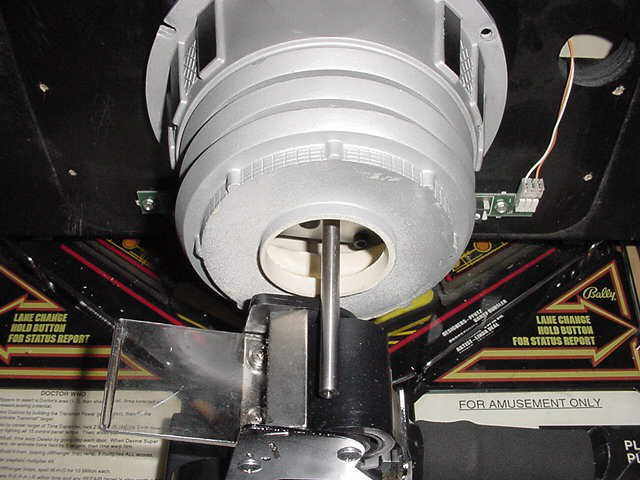
02/04/02 - While the Super Bowl was on, I spent time running between the garage and the living room often with Wobble Head and tools in my hands. The results are that I think I have come up with an order to install the head in that will cause the least amount of time tweaking. The space inside the Dalek's body is cramped at best and the adjustability of Wobble Head to adapt to moulding differences is excellent. Unfortunately, it is a pain to do. I have to say, when it's right, it's like no other mechanism before it. The gap between the head and body can be adjusted so small that you will be impressed. Documentation is proceeding along and is actually about 1/3rd completed. I think I'll have documentation by the time my friend finishes all of the wiring harnesses (which he hates making)! In this same time/space I am shopping a pin so I'll be breaking up my time with this.
I have 2 people reminding me (Vincent and John) that they are buying them so our count for sale is at 8. If you have not sent me an e-mail in the past couple of days saying you're a definite, please do so. I'll add your name to the reserve list.
Now for more Wobble Head Details! I will have my kit today and begin documenting it's installation. The documentation will become available in PDF format prior to the kit's general release. This will give you a chance to go over it and see what will be involved in the installation. Let me state for the record that this will be one of the easiest installs you'll ever do on a pinball machine. My friend has gone to great lengths to make this a breeze to install. An original mechanism would require more work.
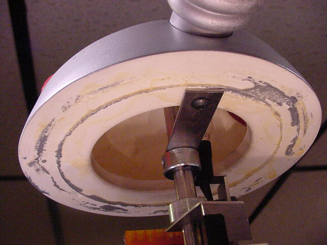
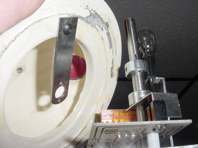
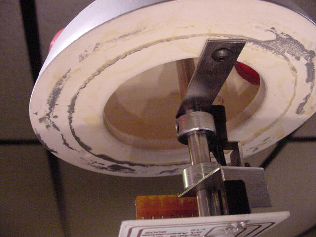
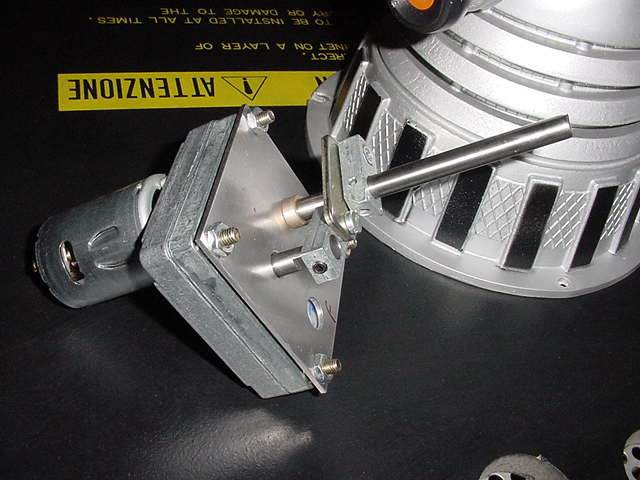
My friend worked out the electronics problems that he was having and reveals in these pictures how the head attaches to the motor. Totally ingenious if you ask me. We also have a few movies for your enjoyment even some of the built in software that you've probably never seen before.
|
|
|
|
| THE ON-LINE VIDEOS |
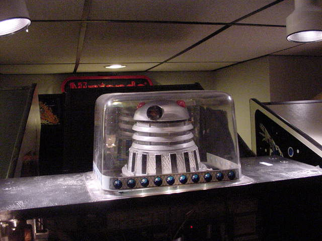
| Away shot of Wobble Head on the Backbox. |
| Close Up of Wobble Head. |
| Wobble Head on the backbox. |
| Software Test Screens. |
01/23/02 - After a few fried optos, we have the opto boards sorta working. We have to work out some details with the speed of the motor in relation to the opto. Things are progressing. We have to get these details worked out before we can make them available. We have been communicating with a couple of people who have knowledge in this area and will update everyone when we get the bugs worked out. It shouldn't be long. Thanks for your patience!
01/13/02 - From these pictures, you'll know this is going to happen and happen soon! My friend sent the following update:
"Here is the week in review.
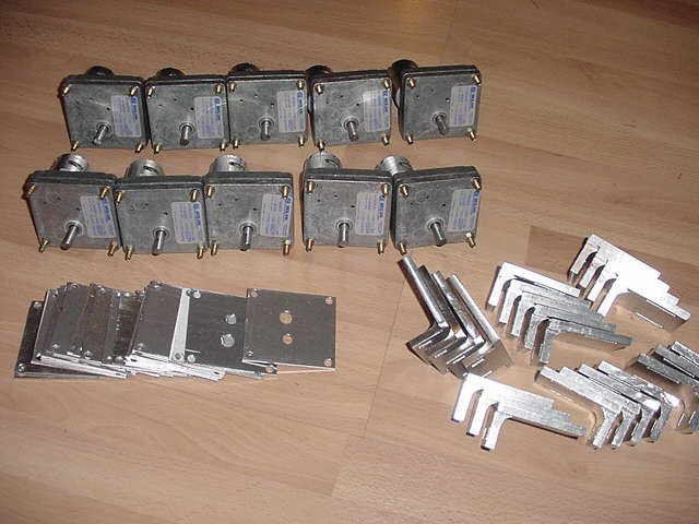
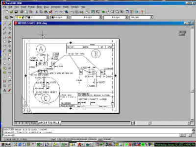
First, I know there has been some speculation from the readers if this project would ever be completed as well as the availability of spare part. First, Look at the pictures. Here we have 10 motors, 20 bottom-bearing plates and 20 motor mounting plates ready to go.
 |
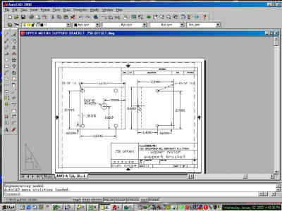
I have the 20 upper motor brackets done as well with the exception of 3 tapered holes that they still need. |
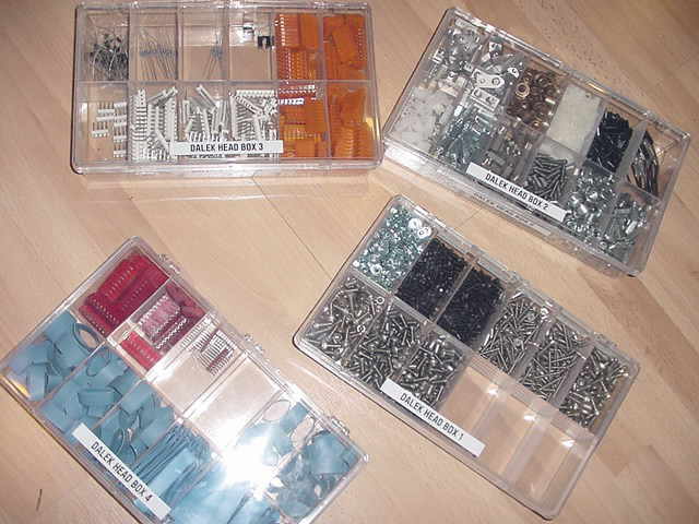 |
I have organized everything I need for an assembly into a box and so far there are 4 boxes of parts. |
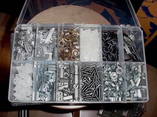 |
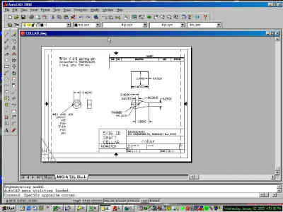
Also in this box (2 upper left spots) is the upper and lower cam lobes. (Enough for 20 as well). |
On the list of the parts left to make are the "B Clip" (provides the back and forth action) and the bottom mounting plate that it all mounts on.
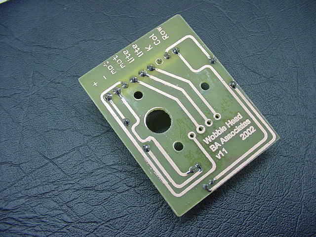
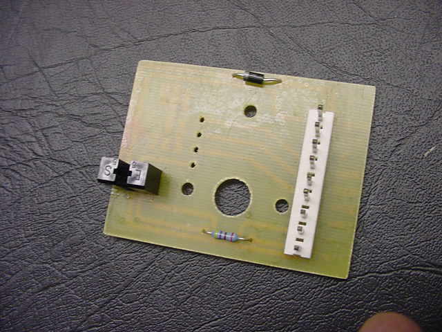
This is ( I hope ) the last revision of the PC board shown top , bottom and mounted with components. The only problem is that the opto I chose doesn't work... Sigh.. I have 20 of a different variation on order and as long as they just drop in I shouldn't need to change the board again.
 |
 |
 |
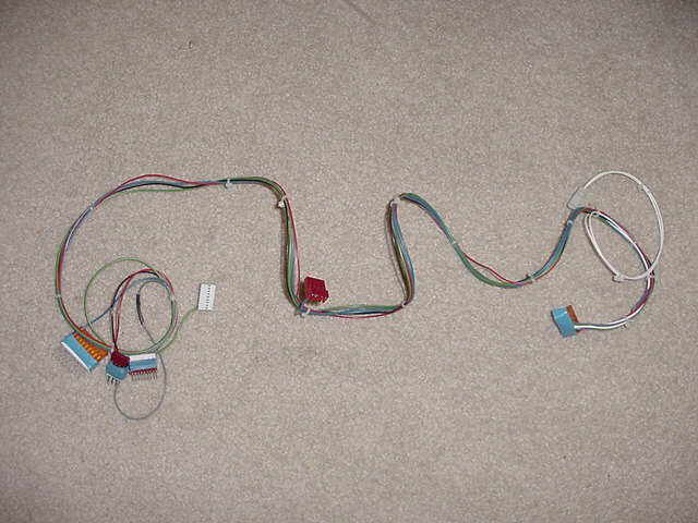
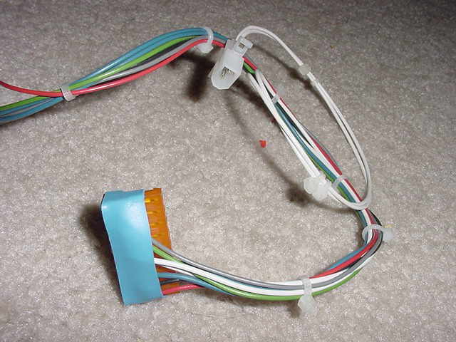
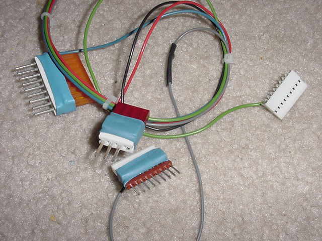
I also made a harness. Now don't look too hard at the 3 pictures because some of the connectors are all wrong. I have corrected this but needed to order more connectors for a 6 conductor plug I didn't plan for. The missing parts will be in tomorrow. What you should look at is the plug and play set up on the harness. This allows you to just plug it all in without hacking up the OEM wiring and will make installation easier for the casual user."
 |
 |
 |
01/02/02 - This thing is getting so close to finished! My friend ran into a few small problems but will resolve them shortly. This is an amazing project. Some friends of mine said "Why all of this to make the head just go back and forth, hardly seems worth it". They obviously don't collect games. I can hardly wait to get mine running! Also the page load times were getting way too long so I converted all the older pics to thumbnails. Click on them to see the "Big Picture". And no, you didn't miss it, there are two updates here, I have a couple of projects that I'm working on that prevented me from making the updates.
"Well, here is today's update although it ends with "back to the drawing board". As you can see from the picture I made my first Opto PCB today.
| Pic 1 is the board before etching: | 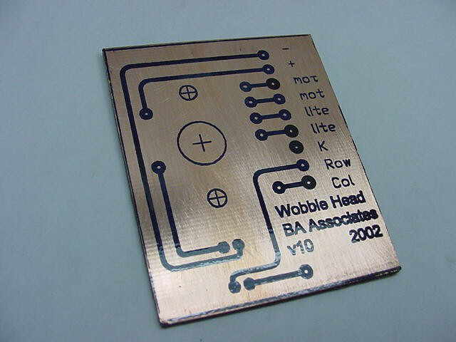
|
| Pic 2 is in the solution: | 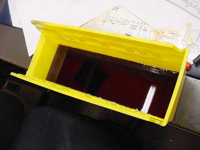 |
| Pic 3 is the finished product: |  |
Pic 4 is where I learned I forgot to consider the swing of the opto's flag and that is comes too close to the connector. |
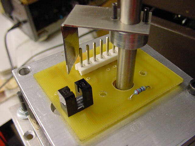 |
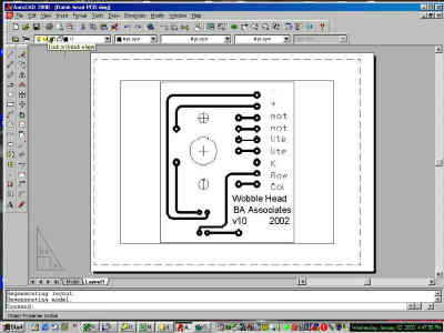
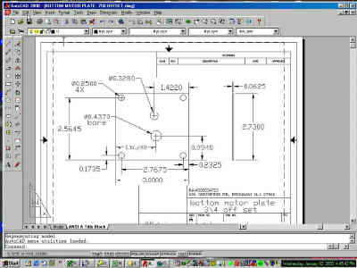
01/02/02 - Another update... "Well we spent the day updating cad drawings and cading out the PC board. If all goes well (aka, we can find all our board making stuff), I should have a etched board by the weekend. I attached some thumbnail pictures of some of the cad work.
I also ordered a crap load of connectors so I can make some wiring harnesses. Ordered a bunch more aluminum and more motors.... parts should be in tomorrow."
 |
 |
 |
 |  |
12/30/01 - It is my opinion that we will have this kit actually finished in a few months. I would suggest that if you are planning to purchase one of these, you start saving now. Unlike other projects, a second run will not probably happen in the near future because of all of the custom parts that are being made for it and an unclear future as to whether we will have access the machines required to make them.
My Friend's Report:"We have nicknamed it the 'Wobble Head' at work. Actually, I need to finish this sooner, rather then later, as I don't know the access I will have to milling machines after February.
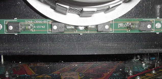
I have started Production quantities of most of the wobble head parts, as of this week. I have no more changes to the motor mount or mechanism with the exception of some additional holes needed to mount the PC board to the motor for the Opto; which I am working on now. I HOPE to have a etched PC board by the end of this week, but the week is short so we will see. I have a friend that wants to help with the PC board so I'm going to have him look at what I drew up and CAD the board for easy etching. The base of the head overhand, over the light strip that I was concerned about last time will not be a problem as the jack plate lifts the whole Dalek above this point. Studying the 2 other web pages of the OEM kit and the other knock off, I'm thinking that the OEM version did the same.
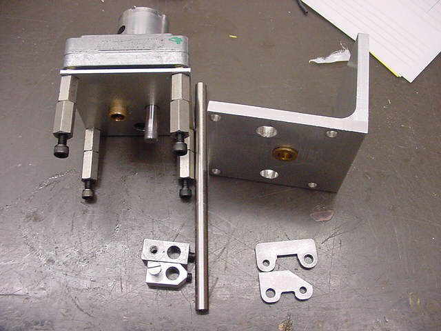
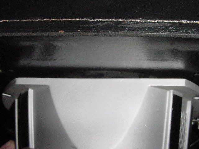
All Daleks are not created the same though. If you look at the pictures, The head you sent me has sinking under where the head goes. The Dalek on the left is the Dalek I pulled off of my machine. For this reason, I felt the need to make the unit as adjustable as possible. The motor unit has slots side to side and slots for up and down as well. I am also going to change the mounting posts from 10-32 to 6-32 as it seems that the hole / slot combination is not 100% the same on all heads. This should make global kit installation easier for the masses. Funny, You would never notice the head is at an angle until you tried to separate it an motorize it. Nothing we can do about the molding.... Just try to make it a perfect as possible.

With those few exceptions, all parts for production are final and CAD drawing for all are complete. I also figured a kick ass way of attaching the Dalek head to the shaft, and centering it, and making it anti rotational yet still easily removable.... But that will have to wait for next time as those parts are not done yet :-)"
 |
 |
 |
12/21/01 - No information yet, but clicking on THIS (350K MPG file) says VOLUMES! Assembled and working head. We still need a PCB and lighting, but this is a WOW!
12/16/01 - Good News. Still not sure of the future, but we have an update! YEY! I was really surprised when I got this message today as I know he's got a lot of other things on his mind. Click on the word MPEG in his text to see a new (351K) video of it in motion. Here's his update:
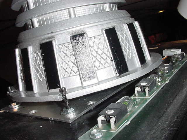
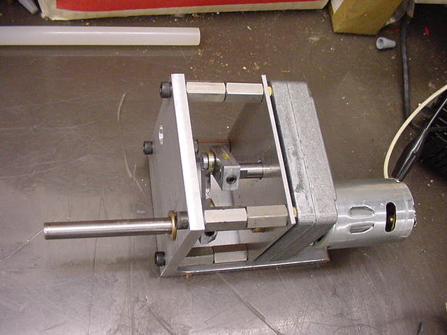
"Its been a few weeks since the last Dalek head update so here is the scoop and new pictures. I basically redid the whole cam set up since I showed you last. The picture shows the old part on the top and the new.. (re-modified again) part on the bottom. I redid the motor lobe, making it smaller and then redid the connecting arm, making that smaller as well. you can also see from the picture, I move the output shaft for the 4th time. All this change reduces the "back lash" you noticed when I showed you last time (when I, Al saw it working for real, it was going back and forth, but jerking at the end) and slows the whole motion down for operation on 24 volts. The MPEG is now being fed @ 24V and the vice grip is only there so you can see the motion :-)
The good news is that is it finally centered and inside the head. The body will need to be raised about 1/4 of an inch, but that seems to be what was needed for the prototype anyway and is never seen because of the "blue dot sticker that covers the Dalek's dome. The only other piece of info is that I may need to move the GI light in front of the robot as I need another 1/4 inch. It looks like I may be able to sneak the PC board back Under the body or above the body But as you see nothing is secure, just held in place by my tape gun :-)
 |
 |
 |
 |
12/05/01 - Bad news. My friend's company is closing the plant he works in. Until he can secure a new position, the project is on hold. Trust me, I'm disappointed as well, but he has more important issues to pursue. If you know of anyone looking for an automation engineer in the Northern NJ / Lower NY area, please contact me (al@alsarcade.com) with the information. I'll send a mailing out to everyone when the situation changes. Thanks for your interest!
11/30/01 - "Well here is today's update.. Busy day.. Updating CAD files and in the mill. I remade the bottom motor shave plate as the old one had way too many holes in it. Also made the top plate and assembled it for a test run... Its ALIVE... I'm not 100% sure the output shaft is where it needs to be but we will see later.
A 343K Mpeg of it running attached although it is only running on 12 volts and it is a 24 volt motor so its a little slow.
11/28/01 - "Latest status is: I got a bunch of Optos and a new bulb holder for the Dalek head flash on Monday. I started working out the cam motion. I didn't like the first run and am trying to get a better center on the shaft. But I had to order stock for that and it is not here yet."
11/25/01 - "The motor plate's shaft placement is all wrong, so Ignore that... I'm moving it (for the 3rd time) tomorrow. Looks like the motor will drop right into the existing holes for the light bulb so that's Cool.... So far it looks like the only new holes to be added in the back box will be 4 wood screws to mount the jack/motor plate"
 |
 |  |